Nu-Bolt & I-Rod Pipe Supports by Deepwater

The Problem
Corrosion at pipe supports is one of the leading causes of process piping failures. It is the beam supports and saddle clamps that have historically caused the majority of problems. These have the following undesirable features in common:
- Crevices – the formation of a crevice at the pipe surface.
- Water Entrapment – water is trapped and held in contact with the pipe surface.
- Poor Inspectability and Maintainability – virtually impossible to paint or otherwise maintain; visual and/or NDT inspection are often difficult.
- Galvanic Couples – even when both the pipe and support are steel, the metallurgical differences can still provide enough potential difference to drive a corrosion cell.
The Corrosion Mechanism:
- Water is trapped.
- The paint system fails (atmospheric coatings soften in immersion service).
- Corrosion is initiated.
- Corrosion undercuts paint film.
- Crevice corrosion starts.
- Pipe fails.
|
The Solution Nu-Bolt™ and I-Rod® have been specified on thousands of offshore production platforms since 1987. They simply and economically address the root cause of crevice corrosion by:
|
 |
 |
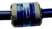
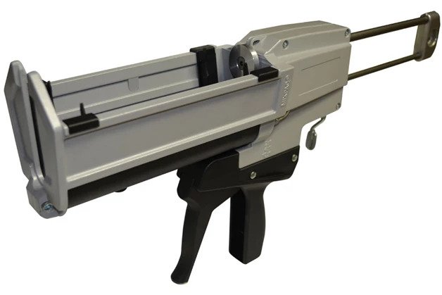
Nu-Bolt™
Designed by corrosion engineers, the Nu-Bolt assembly combines the half-round I-Rod support with a modified pipe U-bolt. A variety of corrosion-resistant treatments provide reliable, long-term service in the harsh operating environments associated with offshore oil and gas production and coastal process facilities.Polyshrink is applied over the shank of the Nu-Bolt to protect the paint system during installation. Polyshrink is not designed to protect the Nu-Bolt. The material is a cross linked, high-compressive-strength, UV-stable polyolefin. It can remain in service in temperatures up to 230 °F (110 °C).Coatings - The Nu-Bolt is available in 316 SS or carbon steel with one of two coatings: Hot-dip galvanized or SermaGard®. SermaGard is a corrosion-resistant coating reliable in even the harshest offshore conditions.Half-round I-Rod support - The standard I-Rod material works extremely well for most process piping conditions. In situations with extreme operating temperatures, Deepwater can substitute the more resistant I-Rod HT material.I-Rod®
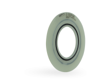
I-Rod® is a high-strength thermoplastic rod in a half round configuration. I-Rod is inserted so the round surface interfaces with the pipe.The half round profile:
- Minimizes contact crevice, and thus eliminates moisture retention.
- Provides a standoff between the pipe and support, and thus:
- Insulates electrically.
- Improves maintainability.
- Improves inspectability.
The high-strength thermoplastic material also:
- Provides excellent compressive strength.
- Is UV stable.
- Has a low friction coefficient, which assists in pipe fitting when used as a beam dressing, and reduces coating damage during new construction.
When used independently as a beam dressing, I-Rod® is typically supplied in 5’ and 10’ lengths.
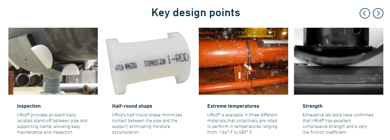
Key design points
Half-round shape
The I-Rod's half-round shape minimizes contact between the pipe and the support, eliminating the crevice. Keeping water out minimizes corrosion.
Maintenance
The Nu-Bolt assembly provides an electrically isolated stand-off between the pipe and the supporting beam or saddle clamp. This allows for easy maintenance and inspection, while preventing galvanic corrosion between dissimilar metals (the pipe and support).
Durability
I-Rod also has excellent compressive strength and a very low friction coefficient. Nu-Bolt assemblies have been in continuous operation since 1989 with no reported failures.
Specifications
Below are the basic specifications for the Nu-Bolt Assembly, including the dimensions of the entire assembly (imperial and metric), I-Rod and I-Rod HT specifications, as well as specs for the polyolefin (heat-shrink) used to coat the U-bolt. Deepwater also offers PEEK material for environments that prove too severe for either (though these instances are rather rare). For information on PEEK or specifications for any other aspect of Deepwater's pipe support systems, please contact us.
Note: The information given herein is believed to be reliable. However, no guarantee or warranty of any kind is implied with respect to accuracy or completeness of these data.
Nu-Bolt pipe bolt dimensions
| Nominal pipe size | Bolt stock Ø” | U-Bolt height A |
Thread length B |
Inside gap C |
Leg center D |
||||||
|---|---|---|---|---|---|---|---|---|---|---|---|
| in | mm | in | mm | in | mm | in | mm | in | mm | in | mm |
| 1/2" | 15 | 1/4" | 6 | 3-1/4 | 83 | 2-3/8 | 60 | 15/16 | 24 | 1-3/16 | 31 |
| 3/4" | 20 | 3-5/16 | 85 | 2-3/8 | 60 | 1-1/8 | 29 | 1-3/8 | 35 | ||
| 1” | 25 | 3-7/16 | 87 | 2-3/8 | 60 | 1-3/8 | 35 | 1-5/8 | 41 | ||
| 3/8” | 10 | 3-7/16 | 87 | 2-3/8 | 60 | 1-3/8 | 35 | 1-3/4 | 44 | ||
| 1-1/4" | 32 | 3-3/4 | 95 | 2-1/2 | 64 | 1-11/16 | 43 | 2-1/8 | 54 | ||
| 1-1/2” | 40 | 4 | 102 | 2-1/2 | 64 | 2 | 51 | 2-3/8 | 60 | ||
| 2” | 50 | 4.5 | 114 | 2-1/2 | 64 | 2-7/16 | 62 | 2-13/16 | 71 | ||
| 2-1/2" | 65 | 1/2” | 13 | 5-1/4 | 134 | 3 | 76 | 2-15/16 | 75 | 3-7/16 | 87 |
| 3” | 80 | 5-13/16 | 148 | 3 | 76 | 3-9/16 | 90 | 4-1/16 | 103 | ||
|
4" |
100 | 6-13/16 | 173 | 3 | 76 | 4-9/16 | 116 | 5-1/16 | 129 | ||
| 5" | 120 | 7-13/16 | 198 | 3 | 76 | 5-5/8 | 143 | 6-1/8 | 156 | ||
| 6" | 150 | 5/8” | 16 | 9-1/2 | 241 | 3-3/4 | 95 | 6-3/4 | 171 | 7-3/8 | 187 |
| 8" | 200 | 11-1/2 | 292 | 3-3/4 | 95 | 8-3/4 | 222 | 9-3/8 | 238 | ||
| 10" | 250 | 3/4” | 19 | 13-13/16 | 351 | 4 | 102 | 10-7/8 | 279 | 11-5/8 | 295 |
| 12" | 300 | 7/8” | 22 | 16-1/16 | 408 | 4-1/4 | 108 | 12-7/8 | 327 | 13-3/4 | 349 |
| 14" | 350 | 17-5/16 | 440 | 4-1/4 | 108 | 14-1/8 | 359 | 15 | 381 | ||
| 16" | 400 | 19-5/16 | 490 | 4-1/4 | 108 | 16-1/8 | 410 | 17 | 432 | ||
| 18" | 450 | 1” | 25 | 21-11/16 | 551 | 4-3/4 | 121 | 18-1/8 | 461 | 19-1/8 | 486 |
| 20" | 500 | 23-11/16 | 602 | 4-3/4 | 121 | 20-1/8 | 511 | 21-1/8 | 537 | ||
| 24" | 600 | 27-11/16 | 703 | 4-3/4 | 121 | 24-1/8 | 613 | 25-1/8 | 638 | ||
| 28" | 700 | 31-11/16 | 805 | 4-3/4 | 121 | 28-1/8 | 715 | 29-1/8 | 740 | ||
| 30" | 750 | 33-11/16 | 856 | 4-3/4 | 121 | 30-1/8 | 765 | 31-1/8 | 791 | ||
| 36" | 900 | 39-11/16 | 1008 | 4-3/4 | 121 | 36-1/8 | 918 | 37-1/8 | 943 | ||
| Nominal pipe size | Bolt stock Ø” | I-Rod length E |
I-ROD hole Ø F |
I-ROD size |
I-ROD height H |
||||||
|---|---|---|---|---|---|---|---|---|---|---|---|
| in | mm | in | mm | in | mm | in | mm | in | mm | in | mm |
| 1/2" | 15 | 1/4" | 6 | 2-1/2 | 64 | 3/8 | 10 | 3/4 | 19 | 5/16 | 8 |
| 3/4" | 20 | 3 | 76 | 3/8 | 10 | 3/4 | 19 | 5/16 | 8 | ||
| 1” | 25 | 3 | 76 | 3/8 | 10 | 3/4 | 19 | 5/16 | 8 | ||
| 3/8” | 10 | 3 | 76 | 1/2 | 13 | 1 | 25 | 7/16 | 11 | ||
| 1-1/4" | 32 | 3-1/2 | 89 | 1/2 | 13 | 1 | 25 | 7/16 | 11 | ||
| 1-1/2” | 40 | 4 | 102 | 1/2 | 13 | 1 | 25 | 7/16 | 11 | ||
| 2” | 50 | 4-1/2 | 114 | 1/2 | 13 | 1 | 25 | 7/16 | 11 | ||
| 2-1/2" | 65 | 1/2” | 13 | 5 | 127 | 5/8 | 16 | 1 | 25 | 7/16 | 11 |
| 3” | 80 | 6 | 152 | 5/8 | 16 | 1 | 25 | 7/16 | 11 | ||
|
4" |
100 | 7 | 178 | 5/8 | 16 | 1 | 25 | 7/16 | 11 | ||
| 5" | 120 | 8 | 203 | 5/8 | 16 | 1 | 25 | 7/16 | 11 | ||
| 6" | 150 | 5/8” | 16 | 9 | 229 | 11/16 | 18 | 1 | 25 | 7/16 | 11 |
| 8" | 200 | 11 | 279 | 11/16 | 18 | 1 | 25 | 7/16 | 11 | ||
| 10" | 250 | 3/4” | 19 | 13-1/2 | 343 | 7/8 | 22 | 1-1/2 | 38 | 11/16 | 18 |
| 12" | 300 | 7/8” | 22 | 16 | 406 | 1 | 25 | 1-1/2 | 38 | 11/16 | 18 |
| 14" | 350 | 17 | 432 | 1 | 25 | 1-1/2 | 38 | 11/16 | 18 | ||
| 16" | 400 | 19 | 483 | 1 | 25 | 1-1/2 | 38 | 11/16 | 18 | ||
| 18" | 450 | 1” | 25 | 21-1/2 | 546 | 1-1/8 | 29 | 1-1/2 | 38 | 11/16 | 18 |
| 20" | 500 | 23-1/2 | 597 | 1-1/8 | 29 | 1-1/2 | 38 | 11/16 | 18 | ||
| 24" | 600 | 27-1/2 | 699 | 1-1/8 | 29 | 1-1/2 | 38 | 11/16 | 18 | ||
| 28" | 700 | 31-1/2 | 800 | 1-1/8 | 29 | 1-1/2 | 38 | 11/16 | 18 | ||
| 30" | 750 | 33.5 | 851 | 1-1/8 | 29 | 1-1/2 | 38 | 11/16 | 18 | ||
| 36" | 900 | 39.5 | 1003 | 1-1/8 | 29 | 1-1/2 | 38 | 11/16 | 18 | ||
I-Rod, I-Rod HT and PEEK full material specifications
I-Rod (White) |
I-Rod HT (Amber) |
PEEK (Tan) |
|||||
|---|---|---|---|---|---|---|---|
| Property value | ASTM Test | Metric | Imperial | Metric | Imperial | Metric | Imperial |
| Density, 73º F (23º C) | D792 | 1.41 g/cm3 | 0.0509 lb/in3 | 1.28 g/cc | 0.0462 lb/in3 | 1.31 g/cm3 | 0.047 lb/in3 |
| Tensile strength, 73º F (23º C) | D638 | 64.8 MPa | 9,400 psi | 114 MPa | 16,500 psi | 110 MPa | 16 ksi |
| Tensile modulus of elasticity, 73º F (23ºC) |
D638 | 2.62 GPa | 380 ksi | 3.45 GPa | 500 ksi | 3.44 GPa | 500 ksi |
| Elongation (at break), 73º F (23ºC) |
D638 | 30-60% | 30-60% | 30-60% | 30-60% | 20% | 20% |
| Flexural modulus of elasticity, 73º F (23ºC) |
D790 | 2.76 GPa | 400 ksi | 3.45 GPa | 500 ksi | 6.89 GPa | 1000 ksi |
| Flexural strength, 73º F (23ºC) | D790 | 82.7 MPa | 13 ksi | 138 MPa | 20 ksi | 172 MPa | 25 ksi |
| Compressive strength, 10% def, 73º F (23ºC) |
D695 | 103 MPa | 15 ksi | 152 MPa | 22 ksi | 137 MPa | 20 ksi |
| Coefficient of friction (dry vs steel) | N/A QTM 55007 | 0.25 | 0.25 | 0.42 | 0.42 | 0.40 | 0.40 |
| IZOD Impact (notched), 73º F (23ºC) | D256 | .534 J/cm | 1 ft-lb/in of notch | .267 J/cm | 0.5 ft-lb/in of notch | .534 J/cm | 1.0 ft-lb/in of notch |
| Hardness, Rockwell, 73º F (23ºC) M/R |
D785 | 88/120 | 88/120 | 112/125 | 112/125 | 100/126 | M103 |
| Maximum service temperature | (Long Term) | 83 ºC | 181ºF | 171º C | 340º F | 249 ºC | 480 ºF |
| Deformation under load | D621 | 1.0% | 1.0% | - | - | - | - |
| Melting point | D3418 | 168º C | 329º F | 210º C | 410º F | 340 º C | 644 º F |
| Coefficient of linear expansion | E831 | 97.2 µm/m/ºC | 54 µin/in/ºF | 55.8 µm/m/ºC | 31 µin/in/ºF | - | - |
| Heat deflection temperature, 264 psi |
D648 | 104 ºC | 220ºF | 204 ºC | 400ºF | 160 ºC | 320 ºF |
| Flammability rating | VL94 | HB | HB | V-0 | V-0 | V--0 | V--0 |
| Dielectric strength, short term | D149 | 16.5 kV/mm | 420 V/mil | 32.7 kV/mm | 830 V/mil | 18.9 kV/mm | 480 V/mil- |
I-Rod (cut and drilled) dimensions

| Pipe dia. (in) |
# of cuts (per 10') |
A. Rod length (in) |
B . Hole diameter (in) |
C. Hole center to center (in) |
D. Rod height (in) | E. Rod width (in) |
|---|---|---|---|---|---|---|
| 1/2 | 46 | 2.5 | 0.375 | 1.1875 | 0.313 | 0.75 |
| 3/4 | 38 | 3.0 | 0.375 | 1.375 | 0.313 | 0.75 |
| 1 | 38 | 3.0 | 0.375 | 1.625 | 0.313 | 0.75 |
| 1 | 34 | 3.0 | 0.5 | 1.75 | 0.438 | 1.0 |
| 1.5 | 29 | 4.0 | 0.5 | 2.375 | 0.438 | 1.0 |
| 2 | 26 | 4.5 | 0.5 | 2.8125 | 0.438 | 1.0 |
| 3 | 20 | 6.0 | 0.625 | 4.0625 | 0.438 | 1.0 |
| 4 | 17 | 7.0 | 0.625 | 5.0625 | 0.438 | 1.0 |
| 5 | 15 | 8.0 | 0.625 | 6.125 | 0.438 | 1.0 |
| 6 | 13 | 9.0 | 0.75 | 7.375 | 0.438 | 1.0 |
| 8 | 11 | 11.0 | 0.75 | 9.375 | 0.438 | 1.0 |
| 10 | 8.0 | 13.5 | 0.875 | 11.625 | 0.688 | 1.5 |
| 12 | 7.0 | 16.0 | 1.0 | 13.75 | 0.688 | 1.5 |
| 14 | 7.0 | 17.0 | 1.0 | 15 | 0.688 | 1.5 |
| 16 | 6.0 | 19.0 | 1.0 | 17 | 0.688 | 1.5 |
| 18 | 5.0 | 21.5 | 1.125 | 19.125 | 0.688 | 1.5 |
| 20 | 5.0 | 23.5 | 1.125 | 21.125 | 0.688 | 1.5 |
| 24 | 4.0 | 27.5 | 1.125 | 25.125 | 0.688 | 1.5 |
| 28 | 3.0 | 31.5 | 1.125 | 29.125 | 0.688 | 1.5 |
| 30 | 3.0 | 33.5 | 1.125 | 31.125 | 0.688 | 1.5 |
| 36 | 3.0 | 39.5 | 1.125 | 37.125 | 0.688 | 1.5 |
Polyolefin (heat shrink) specifications
| Property value | ASTM test | Metric | Imperial |
|---|---|---|---|
| Max continuous operating temp | 110 °C | 230 °F | |
| Min continuous operating temp | -55 °C | -67 °F | |
| Tensile strength | D412 ISO 37 | 14.47 MPa | 2,100 psi |
| Elongation | D412 ISO 37 | 550% | 550% |
| Longitudinal change | D2671 | +1%, -10% | +1%, -10% |
| Specific gravity | D792 ISO/R1183 | 1.1 | 1.1 |
| Elongation after heat aging (168 hrs @ 150º C) | D2671 ISO 37 | 500% | 500% |
| Heat shock (4 hrs @ 225º C) | D2671 | No cracking /flowing | No cracking /flowing |
| Low-temperature flexibility (4 hrs @ -55º C) | D2671 | No cracking | No cracking |
| Hardness | D2240 | 50D | 50D |
| Dielectric strength | D149 IEC 243 | 500 KV/mm | 12,700 volts/mil |
| Dielectric voltage withstand (2500V, 6-Hz, 1 min) | UL 486D | No breakdown | No breakdown |
| Volume resistivity | D257 | 1016 Ohm/cm | 1016 Ohm/cm |
| Fluid resistance | MIL-DTL 23053/5, ISO 1817 ISO 37 | Good to excellent | Good to excellent |
| Copper corrosion | D2671 | No corrosion | No corrosion |
| Water absorption | D570 | 0.1% | 0.1% |
| Fungus resistance | G21 | No growth | No growth |
| Adhesive softening point | E28 | 92 +/- 5 °C | 197 +/- 10 ºF |
| Adhesive peel strength (300mm/min @ 23º C) | D1000 | - | - |
| -to steel, alum, P.E. | D1000 | 61 N/cm | 35 pli |
| -to PVC | D1000 | 35 N/cm | 20 pli |
| Adhesive lap shear (1 in / min at 23º C) | D1002 mod | 0.86 MPa | 125 psi |
| Adhesive blocking (30º C) | D1146 | No blocking | No blocking |
| Water penetration | STM 706 | No penetration after 286 hrs minimum of cont. immersion | |
U-Bolt weights and load values
| Nominal pipe size | Bolt stock Ø” | Max recommended load @ 650ºF | Max recommended load @ 750ºF | Approximate weight with nuts (does not include I-Rod) |
|||||
|---|---|---|---|---|---|---|---|---|---|
| in | mm | in | mm | lbs. | kg | lbs. | kg | lbs. | kg |
| 1/2" | 15 | 1/4" | 6 | 485 | 220 | 435 | 195 | 0.11 | 0.05 |
| 3/4" | 20 | 0.12 | 0.06 | ||||||
| 1” | 25 | 0.06 | |||||||
| 3/8” | 10 | 1220 | 550 | 1090 | 495 | 0.28 | 0.13 | ||
| 1-1/4" | 32 | 0.30 | 0.14 | ||||||
| 1-1/2” | 40 | 0.33 | 0,15 | ||||||
| 2” | 50 | 0.73 | 0.33 | ||||||
| 2-1/2" | 65 | 1/2” | 13 | 2260 | 1025 | 2020 | 915 | 0.78 | 0.35 |
| 3” | 80 | 0.84 | 0.38 | ||||||
|
4" |
100 | 0.90 | 0.41 | ||||||
| 5" | 120 | 1.00 | 0.45 | ||||||
| 6" | 150 | 5/8” | 16 | 3620 | 1645 | 3230 | 1465 | 2.00 | 0.90 |
| 8" | 200 | 2.30 | 1.04 | ||||||
| 10" | 250 | 3/4” | 19 | 5420 | 2460 | 4830 | 2195 | 4.90 | 2.23 |
| 12" | 300 | 7/8” | 22 | 7540 | 3425 | 673 | 3050 | 7.70 | 3.50 |
| 14" | 350 | 8.30 | 3.77 | ||||||
| 16" | 400 | 9.20 | 4.18 | ||||||
| 18" | 450 | 1” | 25 | 9920 | 4500 | 8850 | 4020 | 13.5 | 6.14 |
| 20" | 500 | 14.6 | 6.63 | ||||||
| 24" | 600 | 16.9 | 7.68 | ||||||
| 28" | 700 | 18.0 | 8.18 | ||||||
| 30" | 750 | 19.1 | 8.68 | ||||||
| 36" | 900 | 23.2 | 10.54 | ||||||
I-Rod load values (when using I-Rod as a beam dressing)
Piping engineers: Use the following maximum loading for each I-Rod. Up to three rods can be used to achieve desired weight loading:
1 in I-Rod 8,000 lb (3636 Kg) 1 ½ in I-Rod 10,000 lb (4545 Kg)
The table below conservatively estimates total weight/foot of pipe filled with water. Multiply this number by support spacing to get total weight loading, then select number of 1 in. I-Rods if pipe is less than 12 in. 1 ½ in. I-Rods are generally recommended for piping over 12 in. Do not mix rod sizes.
Weight (lb) / foot of piping full of water (conservative)
| Nominal pipe size (in) |
Outside diameter (in) |
Std | Sch 40 | X-Strong | Sch 80 | Sch 120 | Sch 140 | Sch 160 | XX Strong |
|---|---|---|---|---|---|---|---|---|---|
| 2 | 2.375 | 6 | 6 | 7 | 7 | 9 | 11 | ||
| 3 | 3.500 | 12 | 12 | 14 | 14 | 18 | 23 | ||
| 4 | 4.500 | 18 | 18 | 22 | 22 | 26 | 29 | 34 | |
| 6 | 6.625 | 33 | 34 | 44 | 44 | 51 | 60 | 68 | |
| 8 | 8.625 | 51 | 54 | 69 | 69 | 86 | 93 | 100 | 98 |
| 10 | 10.750 | 76 | 80 | 94 | 104 | 129 | 143 | 155 | 143 |
| 12 | 12.750 | 104 | 110 | 121 | 144 | 181 | 195 | 215 | 181 |
| 14 | 14.000 | 122 | 131 | 140 | 173 | 217 | 237 | 255 | |
| 16 | 16.000 | 151 | 171 | 171 | 224 | 280 | 310 | 332 | |
| 18 | 18.000 | 183 | 216 | 205 | 282 | 354 | 384 | 418 | |
| 20 | 20.000 | 217 | 261 | 242 | 346 | 432 | 447 | 514 | |
| 24 | 24.000 | 294 | 370 | 325 | 494 | 625 | 678 | 737 | |
| 26 | 26.000 | 337 | 370 | ||||||
| 28 | 28.000 | 383 | 419 | ||||||
| 30 | 30.000 | 431 | 470 | ||||||
| 36 | 36.000 | 593 | 731 | 639 | |||||
| 42 | 42.000 | 780 | 834 |
I-Rod material health hazard data (standard I-Rod material only)
Acute or immediate effects: Routes of entry and systems
INGESTION: Not a probable route of exposure
SKIN: Molten I-Rod® causes thermal burns
EYE: Mechanical irritation only
INHALATION: Shapes not respirable
Nu-Bolt Pipe Bolt Dimensions


There are 2 accessories for the Nu-Blot & I-Rod Pipe Supports: the I-Rod Adhesive and the I-Rod Clip. Details for each accesory can be found below.
|
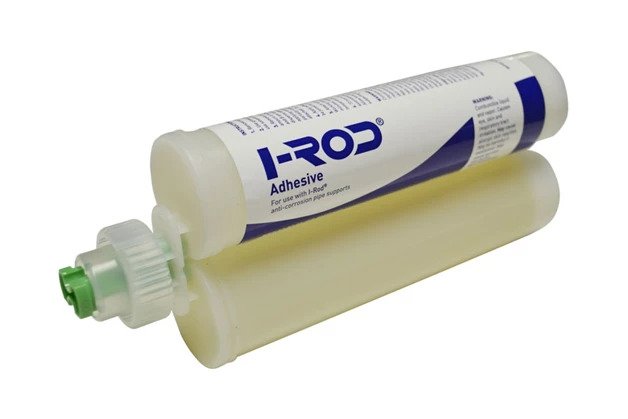
I-Rod® Adhesive™ provides a strong, permanent bond between I-Rod® strips and pipe supportsI-Rod® Adhesive™ is designed to securely anchor strips of I-Rod® in situations where drilling and bolting would be difficult. It’s a great solution for using I-Rod® on solid concrete supports that can’t be fitted with U-bolts, or for locations where drilling through metal is restricted or would require a hot work permit. 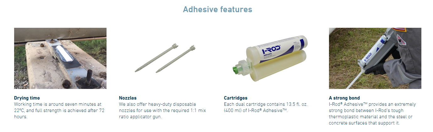 Cartridge Coverage |
|
I-Rod Clip
 |

Questions & Answers
To assist our customers, we have put together answers to the most frequently asked questions regarding I-Rod pipe support systems.
Q: “Is I-ROD made of Teflon?”
A: No, I-Rod is a high-impact thermoplastic material. Teflon would not function due to lack of compressive strength.
Q: “Is the material on a Nu-Bolt Neoprene?”
A: No, it is a cross-linked, heat-shrinkable polyolefin material. Neoprene would have to be vulcanized to stick to the U-Bolt, and would deform too much, and cause problems with moisture.
Q: “What is the maximum piping temperature that I can use I-Rod on?”
A: Normally, at temperatures above 90°C (194°F) crevice corrosion is not a problem, because the water simply evaporates. This is therefore our upper recommended continuous service temperature. The material will, however, perform up to 120°C (250°F), but may experience some slight deformation at the contact area.
Q: “Does the I-Rod create a stress raising point on the pipe?”
A: No, not if the piping is correctly supported along it’s length. If there is noticeable sagging between support points then the pipe is being overstressed, and inadequately supported. Note: I-Rod has been used on hundreds of thousands of pipe supports since 1987 and we have never seen a problem.
Q: “How do I know I’m buying I-Rod and not some inferior copy?”
A: Every shipment of I-Rod is traceable, and is sent with a certificate of authenticity. I-Rod is distinctly marked as such.
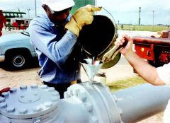
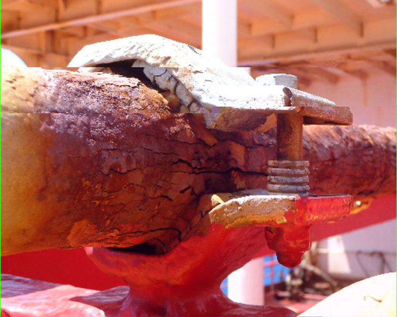
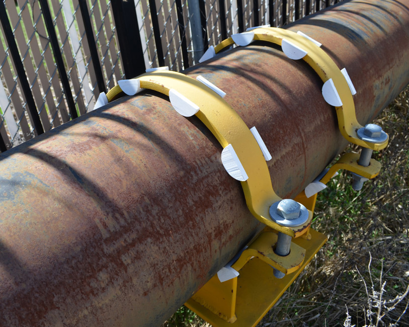
A Case Study of 13 Years of Offshore Exposure
The photos below were recorded during a routine topside inspection of an offshore structure that was installed in 1989. This was the first offshore structure where the I-Rod system was specified for new construction. The total added cost of this system was less than $10,000. The photos demonstrate the success of the system, which has subsequently been used on thousands of offshore structures.
 |
 |
| Installed Nu Bolts - No crevice corrosion. | Fuel gas line, always wet. Green coloration is mold. The beam paint system has failed, but there is not corrosion at pipe support. |
 |
 |
| I-Rod installed under pig launch/receive barrel, bolted to support beams. | I-Rod was found particularly effective on small diameter, screwed piping, which typically has the highest maintenance cost per square foot. |
 |
|
| I-Rod were also found effective on the largest diameter piping of the offshore structure. |