Model UC1, Style A, Underground CP Coupon by EDI
Description
Model UC1 does not have an AC coupon.
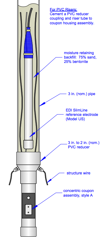
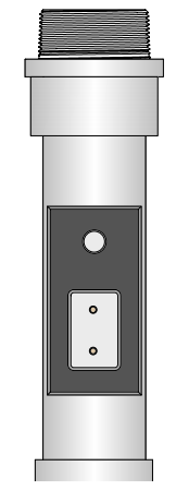
Style A is installed at the base of a test station riser as shown in drawing UC-9. A zinc reference electrode can be installed in the housing as an option.
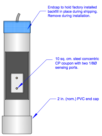
- Patented 10 sq. cm. concentric coupon removes nearly all soil IR drop error in current-on measurements.
- Optional 1 sq. cm. coupon for AC current density measurements.
- Easily fitted to the base of a test station riser or used in a stand-alone configuration when fitted with the optional internal zinc reference electrode.
- Potential measurements are made through the riser tube with either portable or permanent reference electrodes.
The Model UC Underground Cathodic Protection Coupon is fitted to the base of a test station riser. It is designed to allow essentially IR-Drop free measurements with CP current on. The amount of IR-Drop error included in a current-on measurement is negligible and can therefore be ignored in routine measurements. Refer to NACE paper 05039, available on our web site, for quantitative performance data. Many factors contribute to the magnitude of IR-Drop error at any particular site; therefore it is recommended that each installation be calibrated separately.
Specification
- 10 sq. cm. concentric coupon for IR Drop free potential measurements
- 1 sq. cm. coupon for AC current density measurements (Model UC2 only)
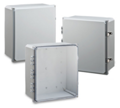
- 2 inch (nom.) PVC pipe construction
- Size - 2 1/2 inches dia. x 10 inches long (6.4 cm x 28 cm long)
- Shipping weight - 6 lb (2.8 kg) plus wire
Style A - Test Station Foot Use Style A when the coupon is affixed to the base of a test station. This style may be ordered with or without the optional zinc reference.
All coupons are internally connected to a 4-conductor 18 ga. cable. The red and black wires are connected to the DC coupon, the blue wire is connected to the optional zinc reference electrode, the orange wire is not connected on Model UC1.
Specify as EDI Model UC1z-xxx-LWnnn where
z = A for Style A test station foot
z = B for Style B self contained
xxx = BDG for no internal reference electrode (only on Style A)
xxx = ZIN for an internal packaged zinc reference electrode nnn = lead wire length in feet.
Note: If no lead wire length is specified, 10 feet (3 meters) will be supplied (LW010).
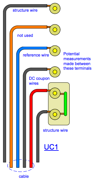
Wiring - Connect a structure wire and one of the DC coupon wires to a terminal pair that can be shunted through a switch or shorting bar. For convenience, a magnetic switch such as EDI Model UI-MS may be used. Connect the other DC coupon wire, the second structure wire, the AC coupon wire and the reference wire each to their own terminals.
Calibrating - Measure the potential when the switch is closed and the instantdisconnect potential as the switch is opened. The difference between the two is the offset potential which should be recorded. This offset potential will usually be less than 10 millivolts.
Measurements - Measurements can be made with the switch or shorting bar closed. In most cases, the offset potential will be sufficiently small that it can be neglected.
Instalation
The Model UC Underground Cathodic Protection Coupon is designed to minimize IR-Drop error in measurements made with CP current on. With this unit the amount of IR-Drop error included in a current-on measurement is negligible and, therefore, can be ignored in routine measurements. Since many factors contribute to the magnitude of IR-Drop error at any particular site, it is recommended that each installation site be calibrated separately.
Installation A
- Remove the protective label covering the steel coupons. Next, remove the red stickers covering the sensing ports. Clean the DC and AC coupon surfaces with alcohol to remove corrosion inhibitor. Place the coupon assembly in a position reasonably close to the structure being monitored. Be sure to orient the coupon assembly vertically with the protective plastic cap at the top. Experience and testing indicate that it is best to face the CP coupon directly toward the structure. Place local soil around the coupon as backfill; make sure no rocks larger than a centimeter in diameter are within a centimeter of the metal plates. Tamp the backfill to ensure it is in good contact with the coupons.
- Remove the protective plastic cap from the top of the coupon assembly; do not remove the cotton cloth backfill retainer. Cement a PVC coupling or reducer to the top of the assembly using PVC cement. Cement riser pipe to the coupling.
- Fill the riser with either screened local soil or a slurry consisting of 25% bentonite and 75% sand or fine fill. A reduced diameter reference electrode, such as an EDI Model US, can be placed in the riser pipe prior to filling. If this is done, then the riser fill must consist of the bentonite slurry.
- Complete the installation by capping the top of the riser pipe as desired. One of the two wires from the DC coupon is to be connected to the structure through an interruptible shunt, such as EDI Model UIMSC or equivalent. The other DC coupon wire is connected to a meter when making potential measurements. See wiring diagram overside.
Measurements
Transfer structure wires to inside the riser tube by passing them through strain reliefs on the transition fitting. The riser tube is to be filled with a moisture retaining backfill. A suitable reduced diameter reference electrode may be placed in the riser tube as shown.
Measurements may be made with either a permanent reference electrode installed in the riser tube, a portable reference electrode placed on the backfill in the riser tube or the optional internal zinc electrode.